In the steam reforming process, a light hydrocarbon feedstock (such as natural gas, refinery gas, LNG, or naphtha) is reacted with steam at elevated temperatures (typically 700-900 °C) and elevated pressures (15-30 bar) on nickel-based catalyst filled tubes to produce a synthesis gas. This gas mainly consists of hydrogen and carbon monoxide, but other gases such carbon dioxide and nitrogen, as well as water vapor are also present. The typical ratio of the gas exiting the reformer is approximately 50% hydrogen, 10% carbon monoxide with the balance being the other gases.
The typical steam to carbon ratio falls in the range of 2.8 to 3.2 to 1. The primary reforming reaction is highly endothermic:
CH4 + H2O <-> CO + 3H2 Dh = +206.16 kJ/mol CH4
To overcome endothermic reaction, the catalyst filled tubes are heated from the combustion of fuels such as natural gas, plant gas and PSA purge gas.
The production plant includes a steam reforming units, named as primary reformer and a secondary reformer. Ceramic catalysts Topsoe R-67, UCI C11, UCI G56, UCI C11-9, Katalco 23 in the shape rings (about 12/5x12 - 16/6x16) and with catalytic coating of 12-20%Ni on alumina and spinel supports are used for primary reforming.
The ceramic catalyst is loaded into the catalytic reformer tubes, which have different design.Some of them are reproduced on picture below:
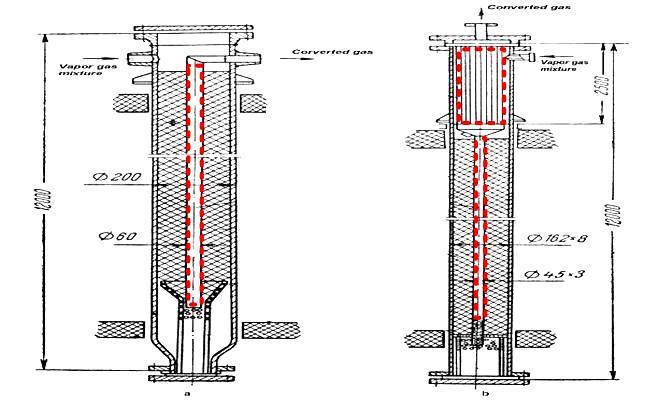
Fig.1a-1b. Catalytic steam reformer tubes
Left reformer provides for top-down gas transportation. The vapor-gas mixture enters into reformer through tube in the upper left corner, goes down through the ceramic catalyst layer and returns up through hollow tube in the center of the reformer.
At first we propose to install our catalysts in some free volumes of the reformer tube, for example, in the central part of the tube (marked in red) to increase the total productivity, not changing design of the reformer tube and regime of its work.
Using our technology we are able to produce the catalytic elements with longitudinal channels of triangular shape in cross-section. The diameter of the element depends on internal diameter of the tube, or other vessel used. The element in cross-section can be adjusted to oval or even rectangular shape.
The most interesting feature of our catalytic element is its low cross-sectional resistance to gas stream (back pressure). That is why we can put our catalytic elements in various free volumes of steam reactor and increase the overall production, not changing gas dynamics of the process.
The catalyst, sprayed on the surface of the element, is practically identical to commercial nickel based catalysts, such as named above. Its adhesion to metal substrate is extremely high and it allows us to forecast a high resistance to gas erosion and thermo cycling.
All the mentioned features of our catalytic block make it unique. Honeycomb structure with low back pressure enables to use it in the volumes where it is not possible to use a normal catalyst. Low weight and electrical conductivity enable to change reformer tube construction to more efficient.
But the main reason to use our metal based catalysts in steam reformer tubes is the opportunity to decrease the temperature gradient between surface of the tube reformer and the center of catalyst loading - in case of using ceramics the gradient is very high because of its low thermal conductivity.
Due to high thermal gradient it is necessary to overheat the external surface of the tube to provide needed temperature in the center of the tube. Due to this overheat outer lay of the tube should be made of very expensive steel but still wares fairly quickly. Use of metal based catalysts gives the opportunity to decrease this temperature. This gives huge economy in energy needed for tube heating and more types of less expensive materials can be used for manufacturing of steam reformer tube itself.
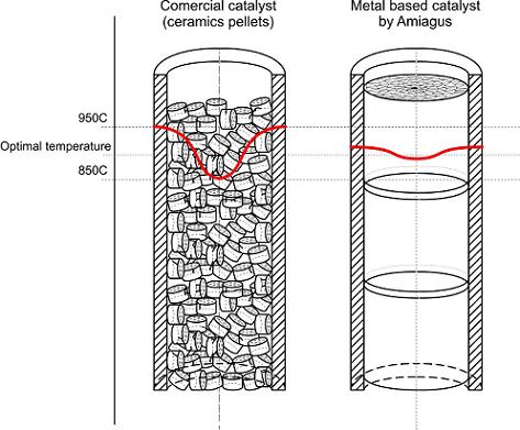
Fig.2 Thermal gradient inside the reformer tube
Summarizing marked features of catalytic elements, developed by Amiagus, we can state that using them for steam reforming process leads to huge economy in energy consumption, expenses on exploitation and equipment revamping also increase in overall productivity. For reformer tube manufacturers these features give opportunity to construct more efficient tubes and use more types of less expensive materials.